
Futaba M402SD07A VFD
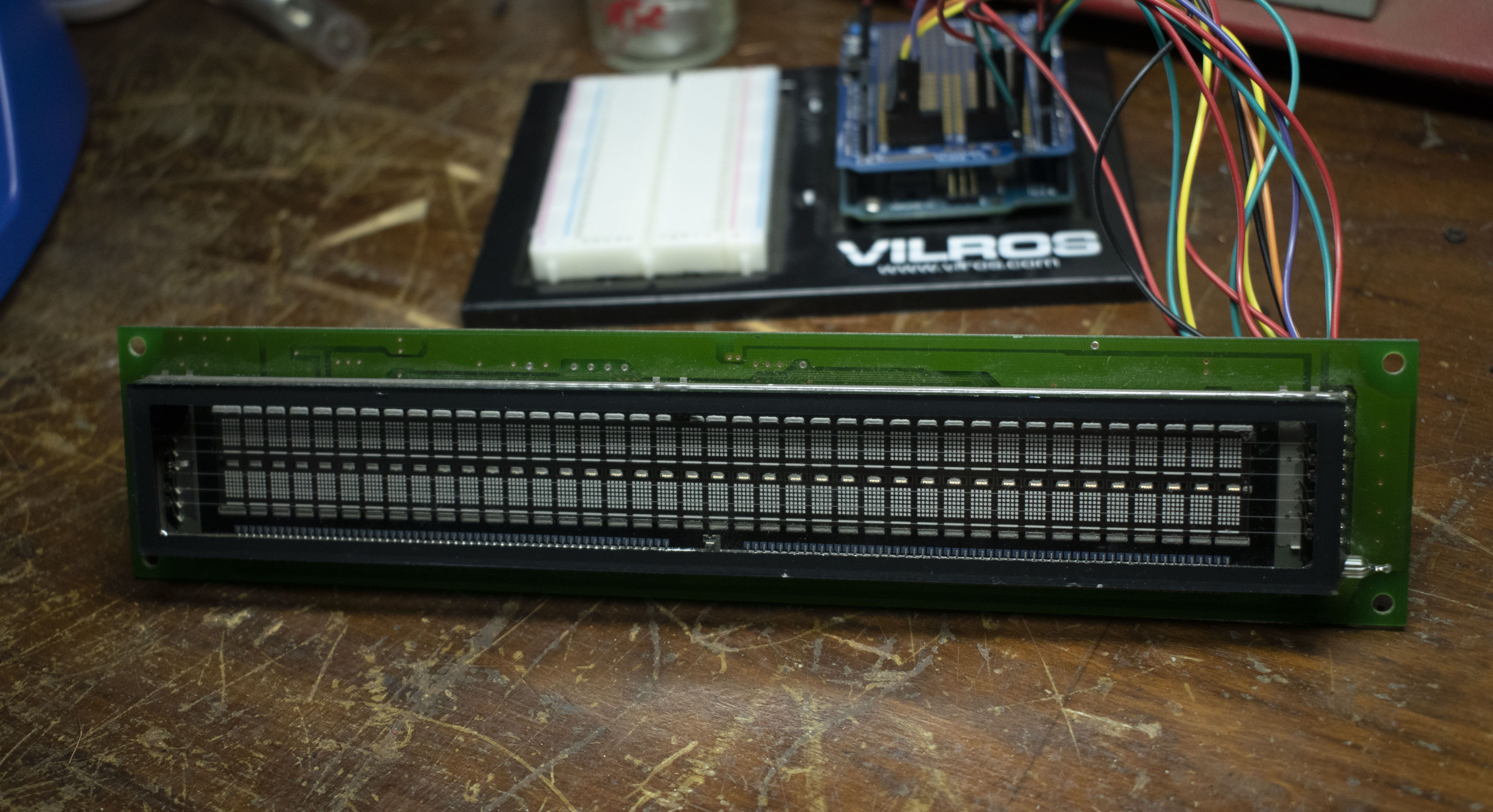
I’ve had this display sitting on my junk shelf for quite a while and decided to finally take a stab at getting it to work with an Arduino Uno. I do not know what the display is originally out of. The display has two 40 character rows for displaying text or symbols. Each character appears to be made out of a 5 x 7 point grid.
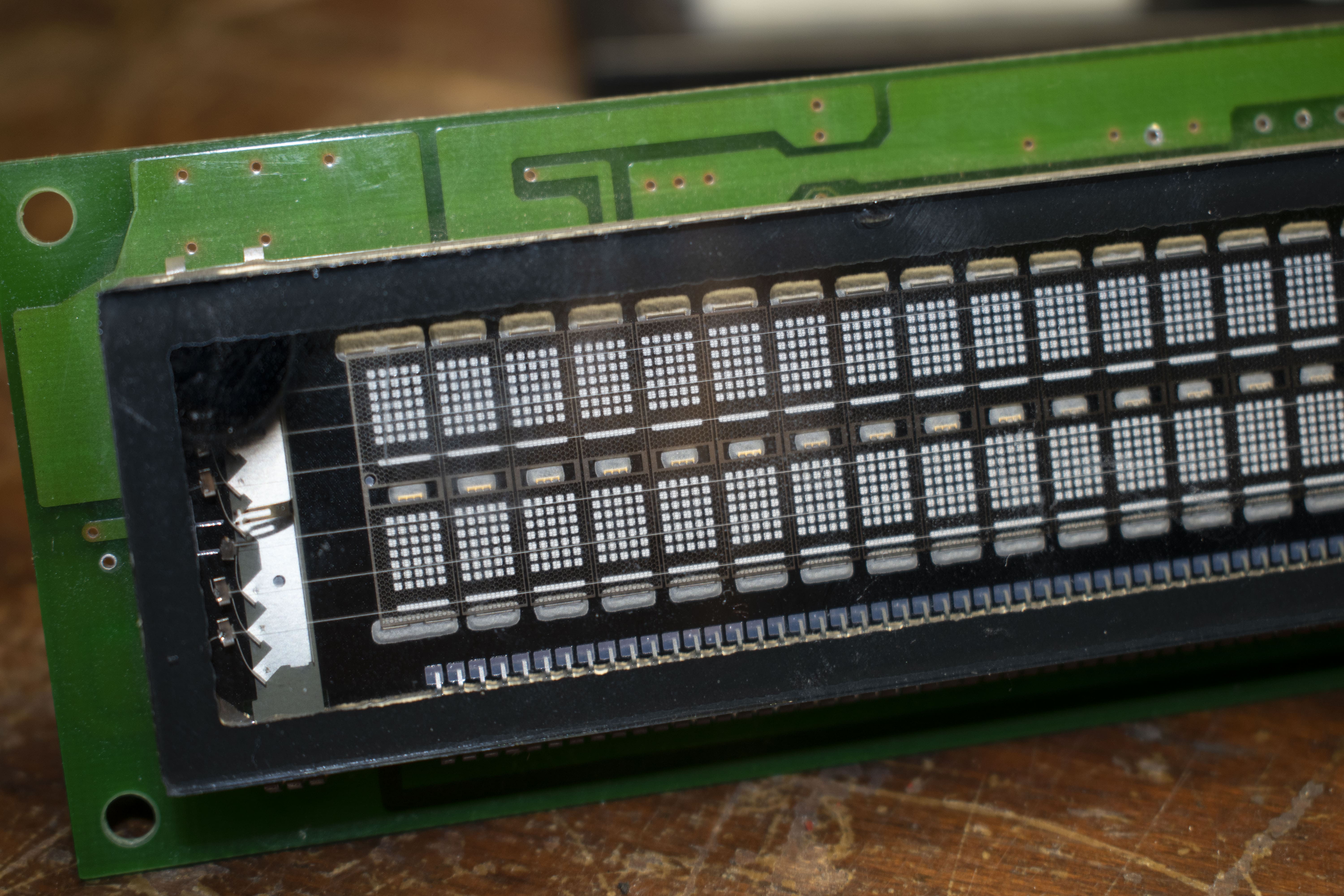
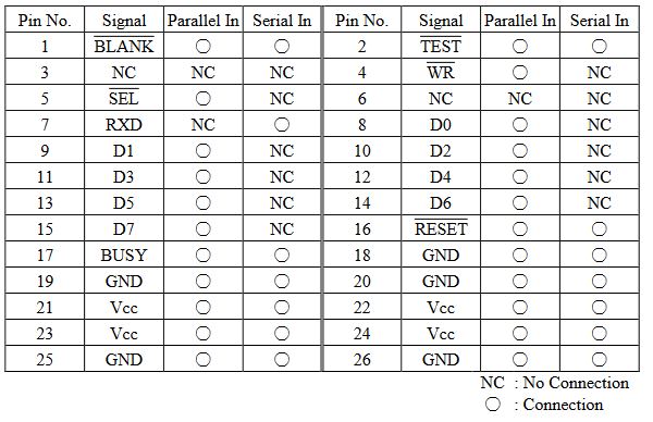
Looking at the back, it has a rather large connector. It is technically called a HIF3FB-26PA-2.54DSA connector. Quite a name. There are some pinouts online thankfully. There are also six jumper solder pads present, probably for adjusting options. Anyway, here’s the pinout:
What is a VFD?
A vacuum fluorescent display (VFD) is a special type of display. VFDs operate on the principle of cathodoluminescence, which is similar to the principle of cathode ray tubes but at much lower voltages. The display consists of a vacuum tube containing a filament, a grid, and a phosphor-coated anode. When a voltage is applied to the filament, it heats up and emits electrons. These electrons are then accelerated towards the anode by the grid, which is negatively charged. When the electrons collide with the phosphor-coated anode, they cause it to emit light. VFDs are known for their bright and clear displays, which can be seen in darkness or full sunlight without straining the eyes.
Where is a datasheet?
After looking far and wide, I was unable to find a datasheet for this particular VFD. However, I was able to find a datasheet for a M402SD07GS VFD display. It can be found here. It uses a different connector but still gives us some good information.
Getting any Output?
The datasheet we have says that J1~J3 are used for selecting the baud rate for serial data input. This display has J1~J6, but a few probably serve the same purpose. We could bruteforce this by soldering one pad, testing, etc. But first we need to make sure that the connection and code is correct. Looking at other similar display pinouts we need to set SELECT high to for serial mode. Plugging the TEST pin into ground confirms the display functions properly as it test and prints its character set. We’ll make sure to set that pin HIGH since we don’t want test mode. There is also a BUSY pin that is typically high when data is processing that we may need to use. So, we can arbitrarily choose some pins on the Arduino for those connections and connect RX to the Arduino’s TX for serial communication. And we can write some code as well:
1
2
3
4
5
6
7
8
9
10
11
12
13
14
15
16
17
18
19
20
21
22
23
24
25
26
27
enum VFD
{
  BUSY = 2,
  BLANK = 3,
  RESET = 4,
  TEST = 5,
};

void setup() {
  pinMode(VFD::BUSY, INPUT);
  pinMode(VFD::BLANK, OUTPUT);
  pinMode(VFD::RESET, OUTPUT);
  pinMode(VFD::TEST, OUTPUT);
  digitalWrite(VFD::BLANK, HIGH);
  digitalWrite(VFD::RESET, HIGH);
  digitalWrite(VFD::TEST, HIGH);
  Serial.begin(9600);
  digitalWrite(VFD::RESET, LOW);
  delay(100);
  digitalWrite(VFD::RESET, HIGH);
  delay(100);
}

void loop() {
  Serial.write("Hello World!");
  delay(15000);
}
First we make an enum structure called VFD to define the pins we are using. Then in setup() we initialize the pins to either be an INPUT or OUTPUT. BUSY is the only pin we’ll need to read (INPUT), and the others are set to OUTPUT. Next we set TEST, BLANK, and RESET to HIGH. Then we enable serial communication at 9600 baud.
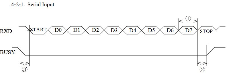
The datasheet we have says that serial uses a start bit, eight data bits, one stop bit, and no parity bits. It is default on Arduino with Serial.begin(). It’s possible to specify it with a second argument like so: Serial.begin(9600, SERIAL_8N1);.
Next we reset the display by setting VFD::RESET to LOW and then back to HIGH. And finally, try to print “Hello World!” and then delay for fifteen seconds.
Now the tedious part, soldering, testing, soldering, testing, etc. After some time, finally some results! With J3 and J1 soldered, junk characters are printed to the screen! No trace of any readable letters but progress! After trying different baud rates, 62500 lets us see the first letter H and then junk. Since we can see H, the baud rate is probably right but it needs a delay between sending multiple characters. In theory, it should be done by reading the BUSY pin. If BUSY is LOW then the VFD is still processing. In practice, this didn’t work though, and I’m not sure why. BUSY would go LOW when processing then HIGH but the data would still get garbled even after sending it only when BUSY was HIGH. What does work is this:
1
2
3
4
5
6
void printText(const char* text){
  for (int i = 0; i < strlen(text); i++) {
    Serial.write(text[i]);
    delay(2);
  }
}
Delaying two milliseconds is enough for the device to process the character! Tada!
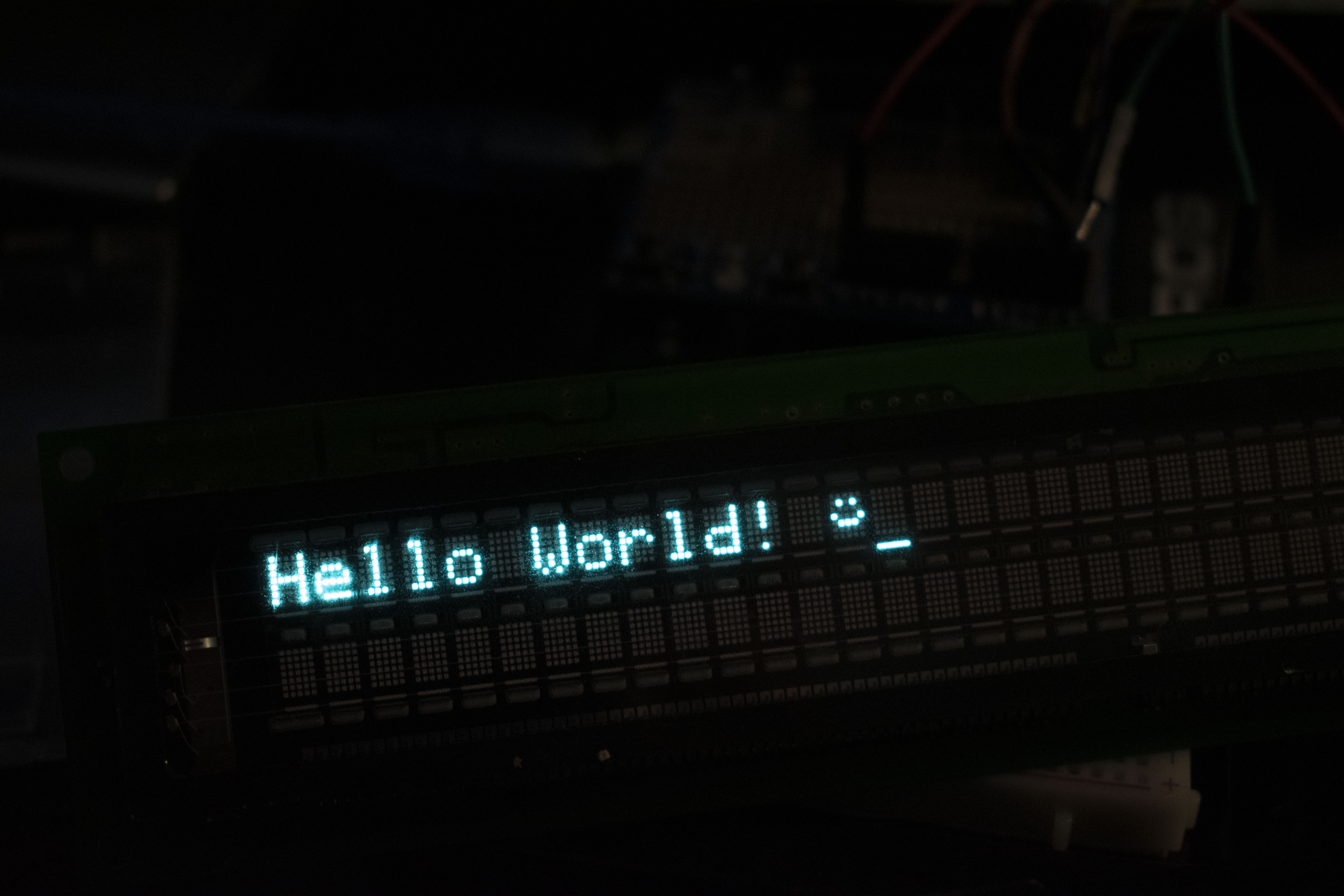
We’ll come back to the smiley face in bit ;)
Control Codes?
The data sheet we have says that sending certain values performs actions on the device. Such as backspace, tab, etc. The values given range from 0x04~0x1F. These values can be sent just like we would send it a ASCII character over serial. So how do we figure it out? Bruteforce and persistence. Print some characters, send a command, print some characters and note the result. Here’s what we get:
0x03: Hides six characters and then continues?0x04: Hides one character and then continues?0x08: Backspace.0x0A: Moves cursor to another row.0x0B: Moves cursor to the top left.0x0C: Shift cursor to the bottom row, leftmost column.0x0D: Shift cursor to the leftmost column of current row the cursor was on.0x10: Hides one character and continues?0x11: New text is added to the right of text already on a row.0x12: New text is added to the right, then rows are shifted upwards.0x14: Display turns off, but text is still present in memory.0x15: Display turns on, any text is displayed.0x16: Hides the flashing cursor.0x17: Turns to flashing cursor on.0x18: Turns display off and can’t be tuned back on.0x1C: Shift cursor right.0x1D: Shift cursor left.0x1E: Shift cursor row.0x1F: Reset the display and clear memory.
Values that do nothing are 0x01, 0x02, 0x05, 0x06, 0x07, 0x09, 0x0E, 0x0E, 0x0F, 0x13, 0x19, 0x1A, 0x1B.
Sweet, that’s almost all of them figured out. Many commands are different or just not listed on the datasheet we have, but thankfully some are. The mystery values are 0x03, 0x04, and 0x10. Since these hide a few characters, they probably expect some values passed to the command. Looking at the datasheet we have, 0x10 is listed as Display Position. It expects a byte after to specify the row + column value, so that fits with what we have. We can test it with this:
1
2
3
4
5
6
7
8
9
10
11
12
13
14
15
void sendDisplayPosition(byte row, byte column) {
  byte displayPosition;

  if (row == 0) {
    displayPosition = column;
  } else if (row == 1) {
    displayPosition = 0x28 + column;
  } else {
    displayPosition = column;
  }

  sendCommand(commands::displayPosition);
  sendCommand(displayPosition);
}
This function sets the cursor position so that the next characters we print will start printing from the specified position. The second row is just 0x28 (40) plus the column you want. So all the display expects, is the total number of columns to set the cursor at. Note: sendCommand is just a wrapper around Serial.write() that adds the required delay.
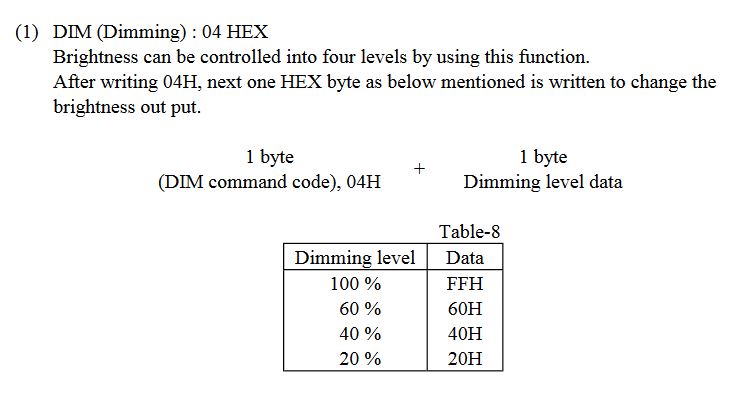
0x04 in the datasheet expects one byte after, just like we found before. This command is Dimming.
This is exactly what 0x04 does on this VFD as well:
1
2
3
4
5
6
byte dim_level[4] = {0xFF, 0x60, 0x40, 0x20}; // Dimming - 100%, 60%, 40%, 20%

void setDimmingLevel(int level) {
  sendCommand(commands::dim);
  sendCommand(dim_level[level]);
}
Setting the dimming level is easy. For 100% (or no dim), you send the control code 0x04 and then send 0xFF. With the function above, we simply call setDimmingLevel(4); for the dimmest screen, or a different dim level.
This leaves us with one mystery control code left: 0x03. Due to how many characters this hides, it expects six bytes after the control code. What could this be?
Custom Characters
After some extensive Googling, some Futaba FVD displays advertise supporting user defined custom characters. If we look at the printable character chart we have, there are blank spaces at the end at positions 0xFE and 0xFF. This could be where it stores the character, it would make sense to be at the end of the other characters. We can test this by sending the control code, then six 0xFF values.
And….. nothing. Characters printed after aren’t hidden now, but trying to print character 0xFF - where our custom character should be - does nothing. After some more testing though, sending the control code, then sending 0xFE, and then 0xFF does work! Trying to print 0xFE prints a character that we could not before sending the control code! So the first byte after the control code is the location of the stored custom character. After more testing, only 0xFC ~ 0xFE work for storing custom characters on this model of display.
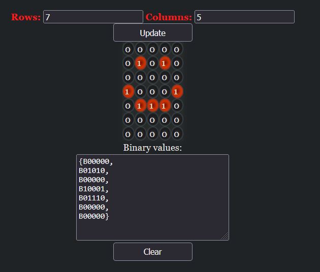
But how are characters printed? Well, we send five bytes of value 0xFF and the character printed has all points on the character lit up. What is 0xFF in binary? 11111111! The binary value of the bytes is used to light up the points, starting from the top left and working right then on to the next row. 1 means a point is turned on and 0 means that point is off. So five bytes is enough data to specify all 35 points with some padding at the end.
The best way I’ve been able to do this is use this wonderful tool matrix font generator tool. Next set the rows to 8 and the columns to 5 to match this specific display’s character size. And then “draw” the character.
Now, we can copy and paste the values into this slightly convoluted CyberChef recipe I made. It will remove everything we don’t want, add padding, and output it in the hex format we need.
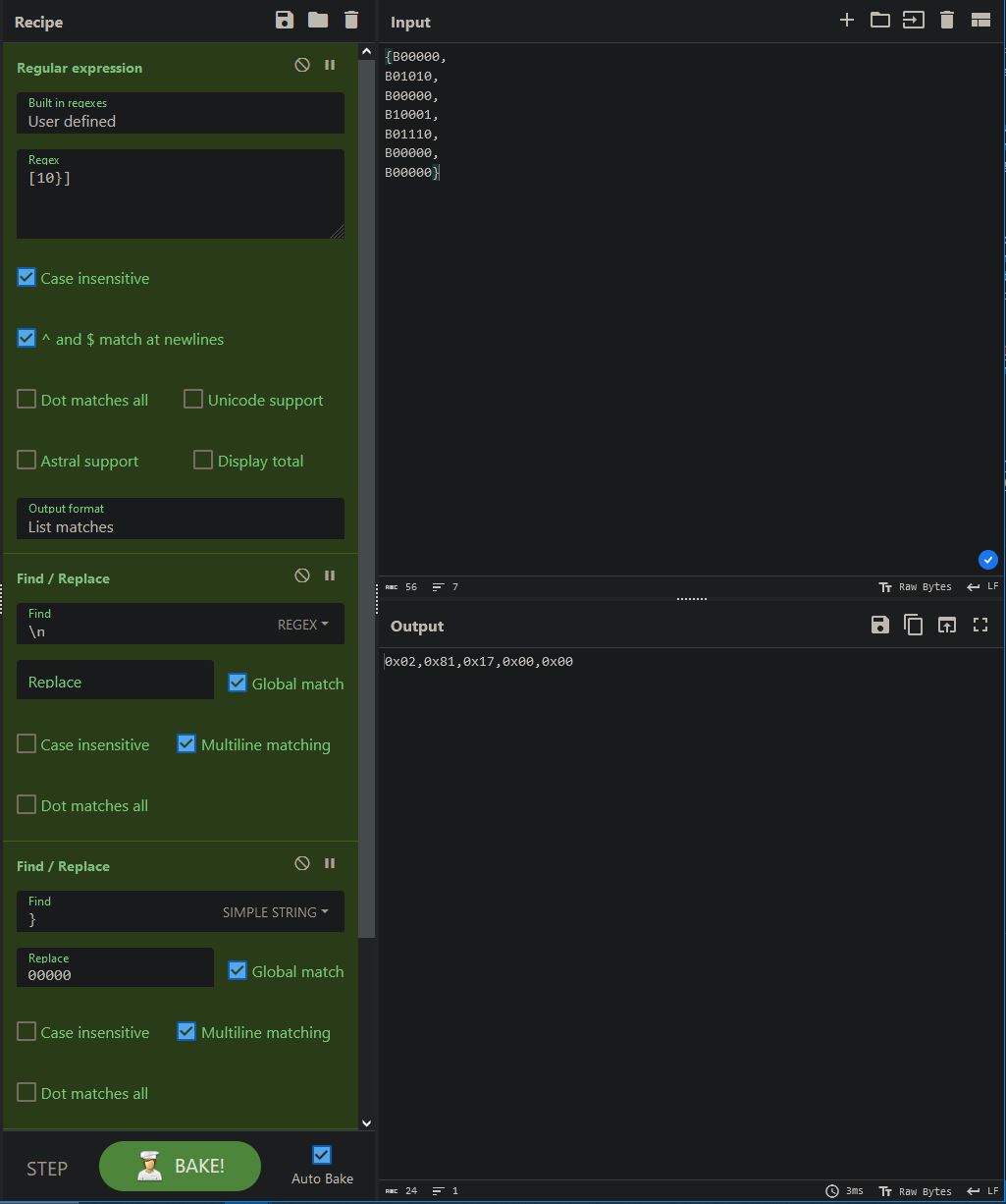
Then we can use these values in the code.
1
2
3
4
5
6
7
8
9
byte smiley_face[5] = {0x02, 0x81, 0x17, 0x00, 0x00};

void createCharacter(byte position, byte data[]) {
  sendCommand(commands::defineCharacter);
  sendCommand(position);
  for (int i = 0; i < 5; i++) {
    sendCommand(data[i]);
  }
}
Calling createCharacter(0xFC, smiley_face); will store the character at position 0xFC in memory, and then we can print it by using Serial.write(0xFC); or whatever wrapper around it we use. And the smiley face will happily be printed.
Control Codes Completed
Now we know enough to name and use all of the control codes.
1
2
3
4
5
6
7
8
9
10
11
12
13
14
15
16
17
18
19
20
21
enum commands
{
  defineCharacter         = 0x03,   // Define Characters (0xFC to 0xFE)
  dim                     = 0x04,
  backspace               = 0x08,
  lineFeed                = 0x0A,   // Move cursor to another row. (Normal Mode) Or shift line up and clear 2nd row. (Vertical mode)
  setHomePosition         = 0x0B,
  carriageReturnLineFeed  = 0x0C,   // CR+LF - Shift down to the most significant digit of bottom row.
  carriageReturn          = 0x0D,   // Carriage Return - shift to the most significant digit of the current row.
  displayPosition         = 0x10,
  displayNormal           = 0x11,
  displayVertical         = 0x12,
  displayOff              = 0x14,
  displayOn               = 0x15,
  cursorOff               = 0x16,
  cursorOn                = 0x17,
  shiftRight              = 0x1C,
  shiftLeft               = 0x1D,
  shiftRow                = 0x1E,
  reset                   = 0x1F,
};
These are all the control codes that I was able to find, aptly named based on what they do and using info from other datasheets.
Scrolling Text
The final thing I wanted to complete is scrolling text across the top row then the bottom row. Sadly, there doesn’t seem to be any sort of scroll mode so it needs to be done using the Arduino software.
1
2
3
4
5
6
7
8
9
10
11
12
13
14
15
16
17
18
19
20
21
22
23
24
25
26
27
28
29
30
31
32
33
34
35
36
37
38
39
40
41
42
void scrollText(const char *text){
  while(true) {
    // Scroll text across the top then bottom row
    int text_len = strlen(text);
    int TOTAL = ROW_COUNT * COLUMN_COUNT;
    sendCommand(commands::cursorOff);

    // Scroll text from the left into the screen
    for (int i = 0; i < text_len; i++) {
          for (int j = i; j > 0; j--) {
              sendCommand(text[text_len-j]);
              // Small delay needed for the motion to appear smooth
              delay(5);
          }
          sendCommand(commands::setHomePosition);
    }

    // Print the full text on screen and delay
    printText(text);
    delay(80);

    // Now scroll the text to the right
    for (int i = 0; i <= TOTAL; i++) {
      // Print a space character to overwrite the first character from the last position
      // Note: You can print text at row:column position or just total columns
      printTextAtPosition(" ", 0, i);
      if (i >= TOTAL - text_len) {
          // If we need to slice off text on the far right, just don't print it
          for (int k = 0; k < (TOTAL - i - 1); k++) {
            sendCommand(text[k]);
          }

        } else {
          // Otherwise, print all the text
          for (int k = 0; k < text_len; k++) {
            sendCommand(text[k]);
          }
        }
        delay(60);
    }
  }
}
The comments in the code do the heavy lifting for explaining here. Scroll the text in from the right printing from the last text first. Then continuously increment the position we start printing the text at. Print a space first to overwrite the first character from the position the text was printed at, otherwise the first character will be in each position after the text moves to the right. Then scroll the text off-screen to the left with some slicing.
Arduino Sketch
Here is the Arduino sketch that includes all the functions and control codes I’ve used on the VFD display.
1
2
3
4
5
6
7
8
9
10
11
12
13
14
15
16
17
18
19
20
21
22
23
24
25
26
27
28
29
30
31
32
33
34
35
36
37
38
39
40
41
42
43
44
45
46
47
48
49
50
51
52
53
54
55
56
57
58
59
60
61
62
63
64
65
66
67
68
69
70
71
72
73
74
75
76
77
78
79
80
81
82
83
84
85
86
87
88
89
90
91
92
93
94
95
96
97
98
99
100
101
102
103
104
105
106
107
108
109
110
111
112
113
114
115
116
117
118
119
120
121
122
123
124
125
126
127
128
129
130
131
132
133
134
135
136
137
138
139
140
141
142
143
144
145
146
147
148
149
150
151
152
153
154
155
156
157
158
159
160
161
162
163
164
165
166
167
168
169
170
171
172
173
174
175
176
177
178
179
180
181
182
183
184
185
186
187
188
189
190
191
192
193
194
195
196
197
const int ROW_COUNT = 2;                              // Total number of rows
const int COLUMN_COUNT = 40;                          // Number of columns per row
byte dim_level[4] = {0xFF, 0x60, 0x40, 0x20};         // Dimming - 100%, 60%, 40%, 20%
byte smiley_face[5] = {0x02, 0x81, 0x17, 0x00, 0x00}; // Byte data for custom character
                                                      // - https://www.riyas.org/2013/12/online-led-matrix-font-generator-with.html
                                                      // - https://gchq.github.io/CyberChef/#recipe=Regular_expression('User%20defined','%5B10%7D%5D',true,true,false,false,false,false,'List%20matches')Find_/_Replace(%7B'option':'Regex','string':'%5C%5Cn'%7D,'',true,false,true,false)Find_/_Replace(%7B'option':'Simple%20string','string':'%7D'%7D,'00000',true,false,true,false)From_Binary('None',8)To_Hex('0x%20with%20comma',0)

/*
Unkown commands:
0x18: Display off? Doesn't like displayOn...

Commands that do nothing(?):
0x01, 0x02, 0x05, 0x06, 0x07, 0x09, 0x0E, 0x0E, 0x0F, 0x13, 0x19, 0x1A, 0x1B
*/

// Commands we do know!
enum commands
{
  defineCharacter         = 0x03,   // Define Characters for UF0∼2 (0xFC to 0xFE)
  dim                     = 0x04,
  backspace               = 0x08,
  lineFeed                = 0x0A,   // Move cursor to another row. (Normal Mode) Or shift line up and clear 2nd row. (Vertical mode)
  setHomePosition         = 0x0B,
  carriageReturnLineFeed  = 0x0C,   // CR+LF - Shift down to the most significant digit of bottom row.
  carriageReturn          = 0x0D,   // Carriage Return - shift to the most significant digit of the current row.
  displayPosition         = 0x10,
  displayNormal           = 0x11,
  displayVertical         = 0x12,
  displayOff              = 0x14,
  displayOn               = 0x15,
  cursorOff               = 0x16,
  cursorOn                = 0x17,
  shiftRight              = 0x1C,
  shiftLeft               = 0x1D,
  shiftRow                = 0x1E,
  reset                   = 0x1F,
};

// VFD Pins we need to control.
enum VFD
{
  BUSY = 2,
  BLANK = 3,
  RESET = 4,
  TEST = 5,
};

void sendCommand(byte command) {
  // Send control codes or characters.
  Serial.write(command);
  delay(1);
}

void createCharacter(byte position, byte data[]) {
  // Send control code
  sendCommand(commands::defineCharacter);
  // Send position/memory location
  sendCommand(position);
  // Send the data
  for (int i = 0; i < 5; i++) {
    sendCommand(data[i]);
  }
}

void setDimmingLevel(int level) {
  // Dim the screen to the specified level
  sendCommand(commands::dim);
  // Write the dimming level data
  sendCommand(dim_level[level]);
}

void selfTest(int delay_time) {
  // Enter self test mode for an amount of time
  digitalWrite(VFD::TEST, LOW);
  delay(delay_time);
  digitalWrite(VFD::TEST, HIGH);
}

void hardwareReset(){
  // Same result as RESET control code, but done using the hardware line
  digitalWrite(VFD::RESET, LOW);
  delay(20);
  digitalWrite(VFD::RESET, HIGH);
}

void hardwareBlankOn(){
  // Same result as DisplayOn control code, but done using the hardware line
  digitalWrite(VFD::BLANK, LOW);
}

void hardwareBlankOff(){
  // Same result as DisplayOff control code, but done using the hardware line
  digitalWrite(VFD::BLANK, HIGH);
}

void sendDisplayPosition(byte row, byte column) {
  // Calculate the display position based on the row and column
  byte displayPosition;

  if (row == 0) {
    displayPosition = column;
  } else if (row == 1) {
    displayPosition = 0x28 + column;
  } else {
    // Invalid row, default to top row
    displayPosition = column;
  }

  // Set the display position using the DP (Display Position) command
  sendCommand(commands::displayPosition);
  sendCommand(displayPosition);  // Row + Column position
}

void printTextAtPosition(const char* text, byte row, byte column) {
  // Print text beginning at a specified column in a specified row.
  sendDisplayPosition(row, column);
  for (int i = 0; i < strlen(text); i++) {
    sendCommand(text[i]);
  }
}

void printText(const char* text){
  // Send text to the device.
  for (int i = 0; i < strlen(text); i++) {
    sendCommand(text[i]);
  }
}

void scrollText(const char *text){
  while(true) {
    // Scroll text across the top then bottom row
    int text_len = strlen(text);
    int TOTAL = ROW_COUNT * COLUMN_COUNT;
    sendCommand(commands::cursorOff);

    // Scroll text from the left into the screen
    for (int i = 0; i < text_len; i++) {
          for (int j = i; j > 0; j--) {
              sendCommand(text[text_len-j]);
              // Small delay needed for the motion to appear smooth
              delay(5);
          }
          sendCommand(commands::setHomePosition);
    }

    // Print the full text on screen and delay
    printText(text);
    delay(80);

    // Now scroll the text to the right
    for (int i = 0; i <= TOTAL; i++) {
      // Print a space character to overwrite the first character from the last position
      // Note: You can print text at row:column position or just total columns
      printTextAtPosition(" ", 0, i);
      if (i >= TOTAL - text_len) {
          // If we need to slice off text on the far right, just don't print it
          for (int k = 0; k < (TOTAL - i - 1); k++) {
            sendCommand(text[k]);
          }

        } else {
          // Otherwise, print all the text
          for (int k = 0; k < text_len; k++) {
            sendCommand(text[k]);
          }
        }
        delay(60);
    }
  }
}

void setup() {
  pinMode(VFD::BUSY, INPUT);
  pinMode(VFD::BLANK, OUTPUT);
  pinMode(VFD::RESET, OUTPUT);
  pinMode(VFD::TEST, OUTPUT);
  digitalWrite(VFD::BLANK, HIGH);
  digitalWrite(VFD::RESET, HIGH);
  digitalWrite(VFD::TEST, HIGH);
  Serial.begin(62500);
  digitalWrite(VFD::RESET, LOW);
  delay(100);
  digitalWrite(VFD::RESET, HIGH);
  delay(100);

  sendCommand(commands::displayNormal);
  createCharacter(0xFC, smiley_face);
}

void loop() {
  printText("Hello World!");
  printText(" ");
  // Print the smiley face
  sendCommand(0xFC);
  delay(30000);
  sendCommand(commands::reset);
}